


- Case Studies
- Wood Chip Barn
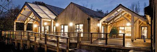
Wood Chip Barn
Introduction
Most timber used in buildings today is machined, glued and fabricated, creating standard products from what was a very non-standard element, a tree. Yet trees have an inherent, natural strength and geometry; the branching forks of a standing tree show remarkable natural strength and material efficiency, able to carry out significant cantilevers with minimal material. A new building at the Architectural Association’s campus at Hooke Park shows how, by using sophisticated digital tools, the inherent structural qualities of natural tree forks can be used to create a large and dramatic structure.
Traditionally, the natural curves and forks of trees were valued and used, particularly for fabricating timber boat hulls in the 17th and 18th century. In the past, boat builders went into the woods armed with a set of templates to find the specific tree forms they needed. Forks and other curved timbers were valued and selected for their shape and also for their grain, and by aligning the grains of branched members which had grown in response to specific loads and integrating these into their designs, boat builders were able to construct stronger vessels. Today, rather than finding forms to fit a predetermined design, the Design + Make team at Hooke Park developed digital tools to create a structure which is derived from the specific character of each component.
Wood Chip Barn, the new building at Hooke Park, provides 400 cubic metres of storage of biofuel for a recently installed biomass boiler which allows the campus to be sustainably heated using its own timber from the 350-acre park. The Barn’s primary timber structure spans 25 metres from front to back and 10 metres from side to side, rising to 8.5 metres at its zenith. The arched structure is covered with a series of timber cassettes consisting of rafters, sheathing, EPDM and cedar cladding. The cassettes are supported at the eaves by a series of delicate steel/timber columns running along the walls; they are clad at low level with horizontal timber planks, and at the rear with a reinforced ‘push’ wall.
The Barn was built by students of the Architectural Association’s Design & Make Master’s course as part of the annual programme at the school's woodland campus in Hooke Park, which engages with design through prototyping and construction of experimental buildings. It joins other innovative buildings on the site, including the Big Shed, a 500 square metre workshop/ shelter (described in a TRADA Case Study in July 2013), which was used by the students to assemble large components of the new building.
The student team at Hooke Park took a photographic survey of the tree fork geometries of 204 standing beech trees to establish which trees to cut down. From this survey 25 tree forks were harvested and a detailed 3-D scan was made of each fork to develop the final configuration of the truss.
Traditional timber framing methods rely on projecting straight centrelines and axes onto irregular pieces of wood in order to work around each piece’s variations. For this project, the workflow – from standing tree to standing building – was organised to a consistent system of geometric referencing (both physically and digitally) to ensure that the 25 tree forks were precisely located and positioned. Three holes were drilled into each tree fork to define a local origin point, an orientation axis and a plane analogous to a local construction plane in 3D-modelling software. These holes were picked up in the 3D-scan and incorporated in to the digital modelling processes; ultimately they were used to support the fork during milling.
The team explored several ways in which the organic forms of tree forks could be organised into a structure. It soon became clear that the naturally forming tree fork joint acted as a rigid moment-resisting connection, a property more common to steel construction. To utilise this ability, the team developed an arched structure using a Vierendeel-style truss system with the forks connected directly to each other to form non-triangulated trusses.
The structure consists of two planar-inclined arched Vierendeel trusses of which the lower chords are connected by lateral elements. The structure lands at four points, the front two slightly wider than the rear, each supported by an inverted tripod leg.
Using the Grasshopper plug-in for Rhino, the team developed a complex procedure (with 56 separate variables) to establish how each tree fork could be best placed within the truss. The strategy that proved most successful was to assign the forks to locations sequentially and in particular to select the most complex truss placements first.
From the optimisation script, a series of possible truss configurations were out-put, and geometries sent to the engineering team for analysis and comparative quantification of the structural performance. By automatically drawing these lines to layers based on local fork diameters, the performance of the truss could be accurately and swiftly evaluated by the engineers for a large number of configurations. One of these was selected and refined. The optimisation script then produced a model with all the geometry needed for the necessary digital fabrication information – 60 curves, 60 points, 60 radius circles, and 20 meshes.
Assembly
The strategy for connections between truss components was to maximise compression transfer by means of timber-to-timber bearing, with steel bolts and split rings to provide tension and shear capacity where needed. The connection bearing surfaces were all milled with a router spindle on a six-axis robotic arm. The router was also used to drill pilot holes, make locating marks for the steel hardware and to drill geometric reference holes for the truss assembly.
Three types of connections were fabricated. A set of 36 axial connections between components along the truss chords was formed by milling matching planar end-faces on the two meeting components which were then connected with a pair of steel crossbolts. These two planar faces, on two different pieces of irregular wood, had to be precisely positioned and oriented 3-dimensionallyso that the compression force would be transferred evenly.
Next, an oblique through-bolted mortise and tenon connection was used to connect the ends of the branch elements to the top chords. The timber interface geometry for this connection was relatively complex; it had to provide sufficient compression area while allowing for diversity in the position of the surrounding wood surface and it had to be formed within the access constraints of the robot arm. A form similar to a truncated elliptical cone was found to best satisfy these criteria. Finally, a simpler set of planar ‘seat’ surfaces were defined and milled, to which smaller reinforcing timber truss members were screw connected.
A large assembly jig was constructed in the Big Shed to join these large and complex building components together precisely. The truss was preassembled in two halves, each approximately 8 metres x 6 metres. The jig had to allow all ten forks to be loosely braced, yet positioned precisely and stably as no connections could be made until all the components had been loose-fitted together. Once this was done, the robot-fabricated top chords were lifted in to place. With all of the major pieces held together as a loose system, the assembly team moved around the truss with hammers, straps and a Rhino model, adjusting each piece as close to its intended position as could be achieved. The two halves of the truss were then moved to site where they were craned in to place and connected.
The ease with which these large pieces came together demonstrates the success of the geometric strategies in processing inherently non-standard materials. With its scaffolding removed, the truss was left self-supporting, its rigid, naturally formed forked components working together to allow a non-triangulated truss to stand with complete stability.
Throughout this work digital technologies were used to convert low-value branched sections of trees into complex and valuable building components with a minimal amount of energy. 3D-scanning, metaheuristic optimisation and customised robotic machining have been combined with traditional timber framing practices, yet without significant increase in production time compared to a similar structure of standardised materials; the fabrication and construction of the building was completed in under six months.
The student team used low-cost software and local resources, proving the viability of a design-fabrication work flow in which the inherent geometric forms of materials can be exploited and deployed.
For architects who seek to add geometric sophistication to their buildings as well as reduce their embodied energy, this project has significant implications. The on-site processing of near-site material by a generic industrial robot arm is an example of distributed manufacturing processes that fully exploit the potential of new digital tools and technologies. Used on materials in this near raw state, digital tools could help to recapture some of the depth of knowledge lost to industrialisation and in doing so elicit exciting and unpredictable architectural forms derived directly from nature.
December 2016
Building Type:Storage barn
Location:Hooke Park, Beaminster, Dorset
Owner/Client:Architectural Association School of Architecture (AA)
Design Team:AA Design + Make
Directors:
Martin Self and Emmanuel Vercruysse
Tutors:
Charley Brentnall and Zachary Mollica
AA Design + Make
Timber Supplier:AA Design + Make
Project Coordination and Site Management:Jack Draper
Timber Elements:Truss roof structure, roof cassettes, external cladding, external wall
Timber Species:Local beech, Douglas fir, larch, Norway spruce, and Western red cedar
Register to download the full case study with images and architectural drawings

Suggested Reading
Specifying externally exposed structural timber
This Wood Information Sheet (WIS) looks at some of the factors to consider when specifying a desired service life for structural timbers that are to be exposed outdoors but not in contact with the ground.
This WIS addresses general principles of structural design only, giving an overview of the...
24/11/2017
Standards Update October 2017
An update of British, European and International Standards relating to timber, including new and revised Standards, those withdrawn or amended and drafts now available for public comment, updated bimonthly.
30/10/2017
List of British Standards October 2017
A list of British Standards which relate directly to timber, updated bimonthly.
30/10/2017